Over the last few months I have been rowing my Acorn 15 regularly because I enjoy it and I need the exercise. My Acorn 15 rowing boat has a fixed rowing position and I decided that it would be a good idea to try rowing with a sliding seat to get a more complete workout. One option would have been to modify the Acorn 15 by fitting a sliding seat. I wasn't keen on doing this because I didn't want to spoil the look of the Acorn 15. It would also have been a compromise solution.

While these ideas were going round in my head I came across the photo below taken by my friend and fellow member of the Wooden Boat Association of Queensland Ian Primrose.

The photo is of a Classic Derwent Skiff designed by Allan Witt of a company called Row and Sail based in Tasmania.

I liked the appearance of this boat which is configured with a sliding seat as shown. The rowing position can be moved forward and an additional seat added for a passenger if desired.

This version of the Derwent Skiff is 5.5 metres (18 feet) long and should weigh around 38 kg. This is less than half the weight of my Acorn 15.


Wednesday 16 May 2018

Launched!

Here is that last photo of the build process. The boat is sitting on the trailer that was built for my Acorn 15. The boat is supported by the rollers along the keel and the cradle towards the bow. The cradle will stop the boat rocking but is mainly there because the winch post support isn't a good fit. The buoyancy tank and outrigger arms assembly will travel in the back of the car with the oars. It's ready to head for the water!


Sitting on the bank at Wivenhoe Dam. All I have to do now is learn a new style of rowing and I'm finding this to be quite difficult.


Friday 4 May 2018

Almost Finished

A couple of days ago I congratulated myself on finishing the last of four coats of varnish on both the outside and inside of the hull but, there is always a but! The outrigger arms and buoyancy tank unit (OAaBTu) is supported in the boat in three places; at the aft end by the outrigger arms resting on the gunwales and at the forward end of the buoyancy tank by a chock on the keel. The height of these chocks is tailored to suit and can only be determined with the OAaBTu in its final position.

Here's a photo of the OAaBTu resting in the boat. There is a lot of fiddly measuring to do to position it correctly; fore and aft, at right angles to the centreline of the boat and centered over the keel.


The height of the chock under the forward end of the OAaBTu is adjusted until the outrigger arms sit nicely on the gunwales

The arms are drilled and counterbored underneath to fit over stainless steel buttons on the gunwales. This has to be done accurately and is time consuming involving measuring, marking and drilling at rightangles to a curved surface.

Here the unit is sitting on its buttons with the fixing screws in place. The stretcher is fixed to the keel with two buttons and these have to be positioned relative to the OAaBTu.


The whole process then has to be repeated  with the OAaBTu in its forward position (used when carrying a passenger).

HereAre three photos of the  "finished" rowing position. The OAaBTu is in the aft position and the buttons for the forward position can be seen on the gunwales.The sliding seat and runners plus the hatch covers are not yet screwed in place but i wanted to see what it all looked like.


The last two bits of woodwork can now be done. The chocks to support the OAaBTu have been shaped, sealed and given their first coat of varnish. While they are getting their additional coats I will finally fix everything else in the boat.


Monday 23 April 2018

First Coat of Varnish.

In the last post I had sealer on the inside of the hull. Since then I turned the boat over , sanded the outside of the hull and gave it two coats of the Wattyl sealer. Here is what the first coat of sealer with 50% thinners does to the plywood.


I had to wait a couple of days for the sealer to harden up enough to sand. in that time I sanded and sealed the rigger arms and the buoyancy tank. Final sanding this morning and then the first coat of varnish applied.  A couple of photos show the hull and the buoyancy tank and rigger arms.


At them moment it is all looking pretty good. There are blemishes but I'm not going to point them out and other people might not notice them!


Sunday 15 April 2018

Sealer On The Inside

With the cross supports fitted under the well decks the final cleaning up of the compartments was a fiddly job because power sanders couldn't be used effectively. Hand sanding did the job.


Here is the aft compartment looking much better with epoxy fillets reinforcing the inside corners.


The compartments were given 3 coats of Wattyl SeaPro TP80 sealer. This is a 2 part sealer witha relatively long pot life and it is quite easy to apply. The first coat was thinned with 50% Wattyl L760 thinners. The warnings on the labels say "good ventilation" and I needed it; for the first time ever the fumes from this stuff made me feel quite woozy. I opened the window and fetched a big pedestal fan!

The decks were glued in place after the sealer dried. Here is a photo of the hull ready for sealing. This is after a LOT of sanding and finishing work - shaping the inwales and adding the breasthook and quarter knees.


Two coats of sealer this time. Again the first coat was thinned 50% and the wood really soaks it up. I will need to buy another 2L kit of the sealer to do the outside of the hull.

Applying the sealer under the breasthook would have been difficult with a straight paintbrush so I modified one. It worked very well.


 Photo of the hull with the 2 coats of sealer. It looks quite good and I think it will look better when it is varnished.


Over the past few weeks I made contact with one of the school rowing clubs as I walked past their premises on the Brisbane River. At the end of the season (about now) the clubs check all their equipment and work out what needs to be replaced, repaired, etc. The result is a number of oars which have reached the end of their life as far as competitive rowing is concerned. The upshot of all this is that I now have two sets of oars, one 2880 long and the other 2850 long. They have carbon fibre shafts and are very light. The only downside to this is that my oars were used by a girls crew and have pink blades and handgrips - easily fixed!


I'm off for a few days R&R with the local wooden boat guys tomorrow and I reaaly feel the need for a rest after all the sanding!

Monday 9 April 2018

Turned Over

It was a relief when I was able to lift both ends of the hull off the mold. All that packing tape and pieces of plastic sheet had done their job. First step was to hoist the boat up in the air so the mold could be pulled out from under it and disassembled. If anyone reading this wants to build a Classic Derwent Skiff the mold is for sale.

 Next step was to lower the boat a bit and rearrange the slings so that it could be turned over. It isn't heavy so this was easily done. With it the right way up the hull was lowered further to sit in the three cradles on saw horses.

The inside of the hull looked very messy with a lot of squeezed out epoxy along the plank laps. a few hours work with a hot air gun and scraper cleaned it up. Here are a couple of before photos.


There are fore and aft buoyancy compartments, basically a bulkhead with a deck on top. The bulkhead is 4mm ply with doublers at the sides and a strip of 12mm square timber across the top. They are trimmed  to fit and then glued in place. Here is the aft one with paver clamps and two horizontal supports to stop it falling over.

The edges of the deck fit on the edge of the middles plank which, due to the angle of the planks is very narrow so two 10mm square strips were added to provide a better gluing surface.


Some cross supports are needed and these can be sen below. Cutting these to length and shaping the ends to fit around the 10mm square stuff was difficult - thank goodness for the gap filling properties of thickened epoxy!

The same was done for the forward compartment.


There are two inwales about 1250mm long. These provide two supporting points for the outrigger arms as well as adding some stiffness to the centre of the boat. The inwales are laminated in the boat from 3 pieces of Western Red Cedar. Here the laminations are being glued over plastic strips and newspare to catch any drips.

The inwales are then clamped in place and the top edge planed down to an angle to match the underside of the outrigger arm. This is a process of plane a bit off and see how it fits until the whole length id done. The underside of the inwale is then planed on the bench; a tricky job because it is hard to hold and banana shaped. Once it is done the ends are tapered and the inwale glued into the boat.


Wednesday 4 April 2018

Almost Ready to Turn Her Over

It has been a week since the last post, quite a lot of time spent int he boat shed and my shoulders ache from hand planing! There doesn't seem to be a way to avoid it. I'm a great fan of power planes but in some places the risk of damage is too great.

The start of the planing was bringing the edges of the garboard planks down flush with the top of the keel. It was awkward reaching up and out to the middle of the boat to do this planing so I climbed up onto the hull to get a better approach. Once done I could prepare a 5 meter long length of 100 x 6 mm hoop pine to cover the edges of the garboard plank. This had a scarf joint in the middle and once ready it was glued down using about 40 200 mm square pavers to hold it down. Once the glue set I climbed back up onto the boat to plane the edges of this keel trim flush with the garboard plank. Unfortunately I didn't take any phots while I was doing this.

The cutwater is made up of 6 x 4 mm thick laminations of hoop pine. Clamping them onto the stem was a tricky exercise involving clamps, threaded rod and a prop from the garage door. I did a trial run of this at the end of the day intending to leave it overnight to encourage the laminations into their new shape. Unfortunately I forgot the prop which was bearing up onto tilting door of the shed and when I closed the door there was a loud bang and stuff flew everywhere. Fortunately no damage done but I set up a notice to remind myself not to do it again when the glue was going off!


While the cutwater was being glued I set up the outrigger arms and the buoyancy tank for gluing. The arms are bolted down to a flat surface using bolts 1600 mm apart. The buoyancy tank is propped up on four legs behind the arms. Two plywood gussets have to glued to the arms, each gusset has 3 holes which have to line up exactly with the 3 holes in the end of the tank. One bolt passes through the gap between the inside ends of the arms (at the top). The other two bolts pass over the arms and just touch them. Glue is applied to the arms and gussets, the 3 bolts tightened into captive nuts inside the tank and an additional clamp used  for good measure. Because the bolts were very close to glued surfaces I smeared them with wax to prevent the epoxy getting hold of them.


The next photo shows the skeg being glued into place using props from the shed roof. This was straight forward but shaping the skeg which tapers from 25 mm thick at the keel down to 19 mm thick at the top edge involved more hand planing.


The gunwales are made up of two laminations; the inner one is Western Red Cedar, light and easy to work. The outer lamination is hoop pine, heavier but tougher to take the knocks. The next two photos show the outer lamination being glued in place. There are a mixture of clamps being used and also so brads through scraps of plywood to stop the joint squirming about.


Before the gunwales could be glued on the cutwater had to be faired to suit the angle of the planks. Because the garboard plank twists as it comes to the stem the angles are constantly changing. This was the main cause of the aching shoulders! It is hard planing on a near vertical surface and a lot of the work had to be done with a rebate plane because of the changing angles. Eventually it was done!

I will do a bit more cleaning up of the outside of the boat and then turn it over. I wonder what the inside of the hull will look like? There will be squeezed out epoxy to clean up but I hope the joints will be tidy enough for me to varnish the inside of the boat.


Monday 26 March 2018

Planking Complete

The planking is now complete. It was basically a straightforward process - cut the scarfs on the ends of the planks, cut the rebates on the bow and stern sections and then glue them in place after beveling the edge of the previous plank. Even though it was straightforward I managed to make a couple of mistakes with the scarf joints. The first mistake was that I didn't apply the clamps carefully enough on one scarf and ended up with a wide strip of exposed white epoxy. This won't look good on a clear finished boat and I am not keen on the idea of inlaying a clean piece of veneer to hide the joint - if it isn't perfectly done it will be as obvious as the white epoxy!

On the middle plank on the other side of the boat I managed to cut the two scarfs on the same side of the centre section. I had already cut the scarfs on the fore and aft sections so I had to cut the incorrect scarf off and make a new one. Cutting the scarf off lost 50mm of the plan's length; the new scarf effectively lost another 50mm. The planks in the kit are cut with some extra lengths to allow a damaged scarf to be recut but doing this would only lose part of the scarfs 50mm length. The result of this is shown here.


The only way to recover from this blunder was to and an extension to the end of the bow section. This resulted in two scarf joints being close together. This is another  nail in the coffin of the varnished boat idea and I will now paint the outside of the boat.

In this next phot the C clamps are clearly visible as are some home made screw clamps where the C clamps can't be used because there isn't enough clearance between the hull and the mold.There are also a couple of good old metal screw clamps in there and a couple of V clamps holding the planks to the stem. These V clamps simply hold by friction but only work on a shallow angle.


Here's the fully planked hull.


at this point I removed all the temporary screws holding the keel, inner stem and transom to the mold and tried to lift the hull off the mold. It wasn't easy because the squeezed out epoxy inside the hull was sticking to the sticky tape and plastic which was in turn stuck to the mold. Fortunately the protective layer of tape and plastic had done its job and I was able to lift the hull up.

While waiting for the planking glue to go off I have assembled the "buoyancy tank". This is a trapezoidal shaped box which sits on the keel in the middle of the boat with the sliding seat mounted on top of it and the outrigger arms attached to the aft end of the box. The top, bottom and ends have corner strips glued to them and finally the sides are glued on. In this photo the sides are being glued in place - a tricky clamping exercise to hold the ends of the side panels down. The tape was sufficient to pull the joints together along the long edges.

After cleaning up the box I couldn't resist a test assembly of the box, the outrigger arms and the sliding seat. Now this weird shaped box begins to make more sense. there is auite a bit more work to be done on this assembly and I will do that while waiting for the epxoy to set on the outer keel, cutwater and skeg.


Friday 16 March 2018

Transom and Garboard Planks

The transom needed a piece of solid timber about 450 mm long by 300 mm wide. I had some nice PNG Rosewood that was 110 mm wide so I ripped 3 pieces 20 mm thick and edge jointed them  before putting the single piece through the thicknesser leaving it slightly over the 16 mm. I wanted to put the boat's name on both sides of the transom using inlayed letters of a different wood. I have a small CNC mill and used this to cut the recesses for the letters in the transom and then the letters themselves. The letters were glued in place with epoxy and then sanded flat.


Now you are probably wondering about the name and why. Remember, Google is your friend! You can't see it but the same inlay is on the other side of the board.

Before the transom could be glued to the end of the keel the keel was lifted off and the edges cleaned up, ie excess epoxy removed. The protective tape, so the hull doesn't stick to the mold was replaced, and the keel put back on the mold. The transom was glued to the end of the keel and screwed to the mold through the corners which will eventually be removed.


Next step was to bevel the edges of the transom so that the planks will lie nicely on it and get a good glue joint. This bevel is tricky, the angle changes continuously. I started out with the power plane with the wooden arm. By riding the arm on the stringers and the next frame the plane cut the correct angle but was awkward to use on a convex curved surface. Then I noticed that my belt sander had a tapped hole in the side so I made a wooden arm to fit it. This worked like a charm and I made a perfect bevel quite quickly.


Here are the two tools with their outrigger arms.


Clamping the planks to each other along the stringers it tricky because a lot of clamps with a long reach are needed. Allan Will suggested C clamps and wedges. I have used this approach before but needed to make a new set. Here they are, various thicknesses of scrap plywood (10, 12, 14, 16 mm thick) cut on the bandsaw. THere are 50+ of them in the stack. They are used with wedges which I have a heao from previous boats.

Preparing the garboard planks (3 each side) involved cutting 50 mm long scarfs on the ends, a rebate or gain at the bow and stern and, because the transom is curved where the planks land cuts had to be made along the inside of the planks so it would bend to the curve.

Here a rebate is being cut in the standard way using a rebate plane.


The cuts so the plank would bend were made with a Dremel with a 1 mm router bit. The Dremel was slide down a ramp so the cut went from the surface to about 4 mm deep in the 6 mm thick plank. Having made one cut the ramp was moved to the next position and another cut made.


Here is a plank with the cuts, they are about 12 mm apart and 200 mm long.


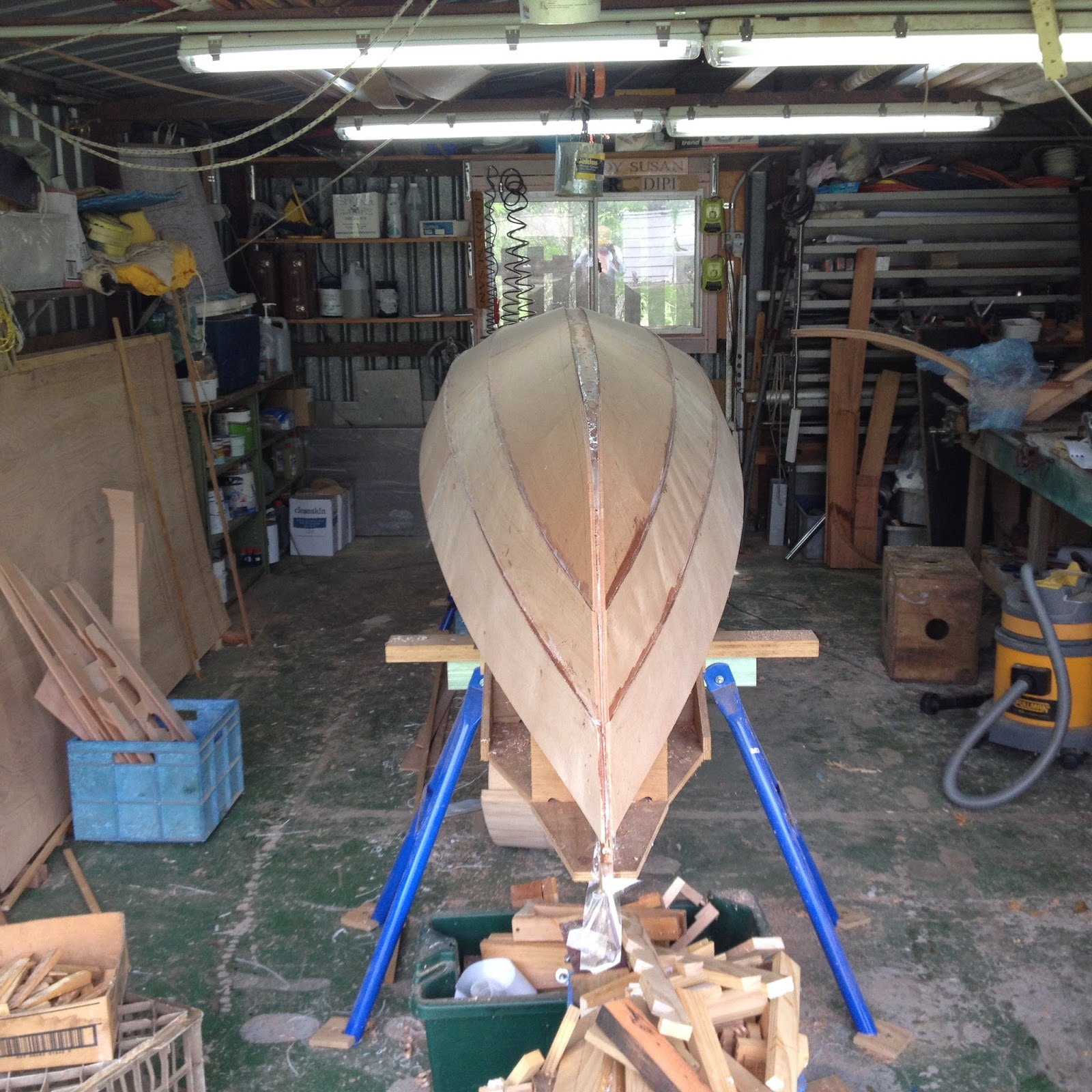
Here is a view from the stern  with 4 out of the 6 planks fitted. The planks are held down by screws along the keel where the holes will be covered by the outer keel.


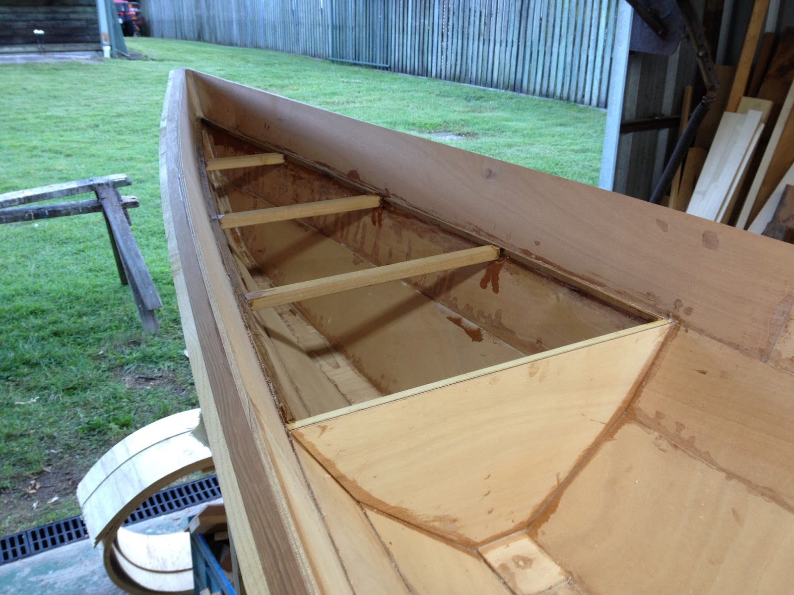
This is a view from the bow with the forward garboard sections being trial fitted. More of the Vee shaped blacks were needed to pull the planks together around the stem but using them avoided screw holes which would have been visible in the finished boat.


Last photo shows the stern section of the  middle plank being glued in place.  Pulling this planks down onto the curved transom was difficult and needed some messy work with a long clamp and a spanish windlass.


More planking tomorrow but then I am going sailing for a week with some of the WBAQ members at Lake Cootharaba.


Gone to a New Home.

 Sadly I have parted with my Derwent Skiff. I loved the feeling of flying over the water that came with the long oars and sliding seat but t...